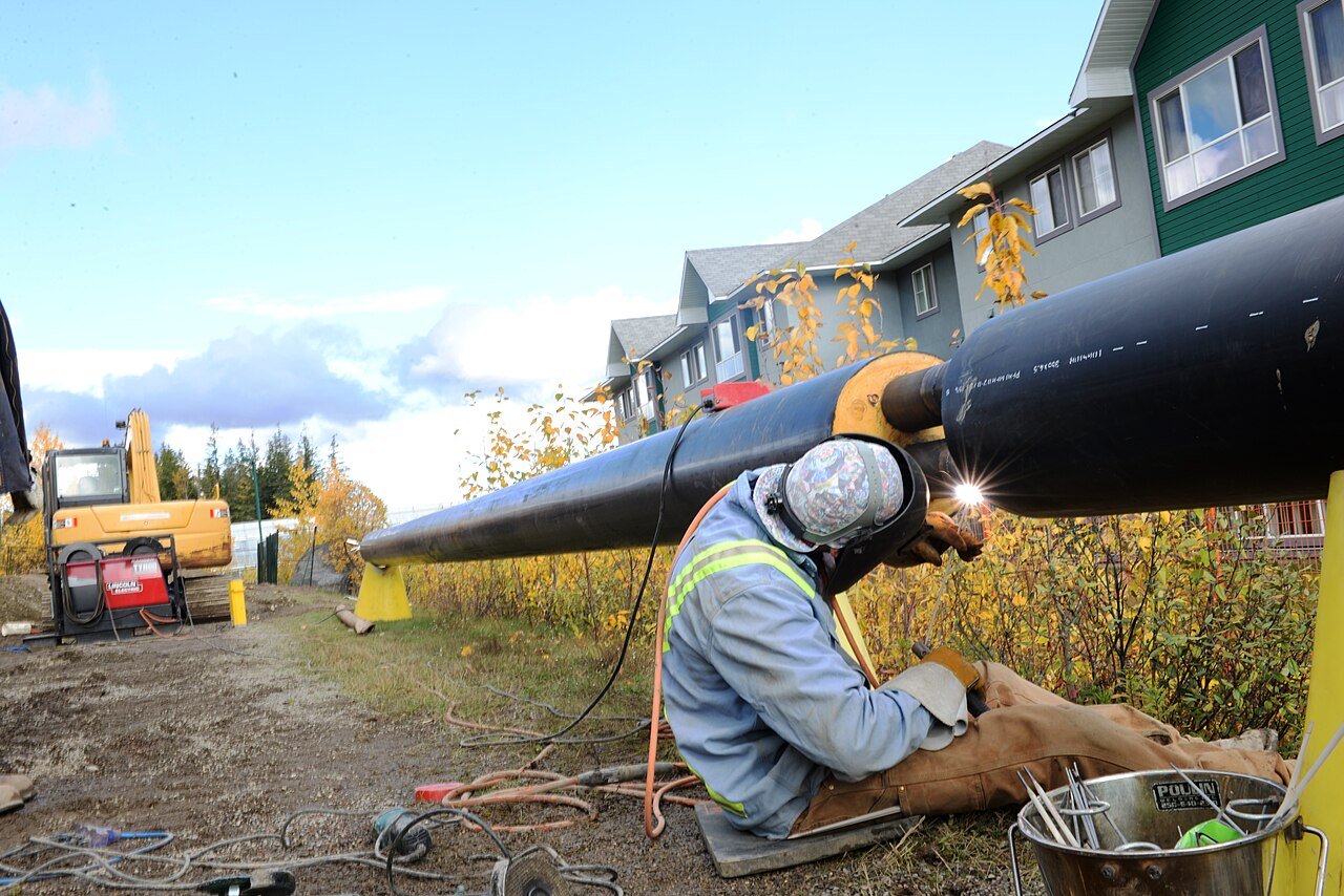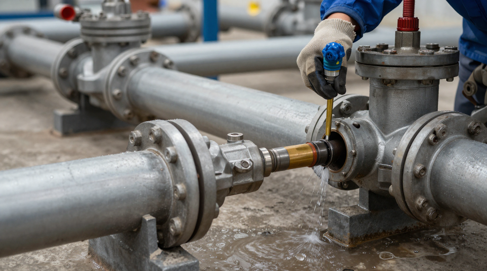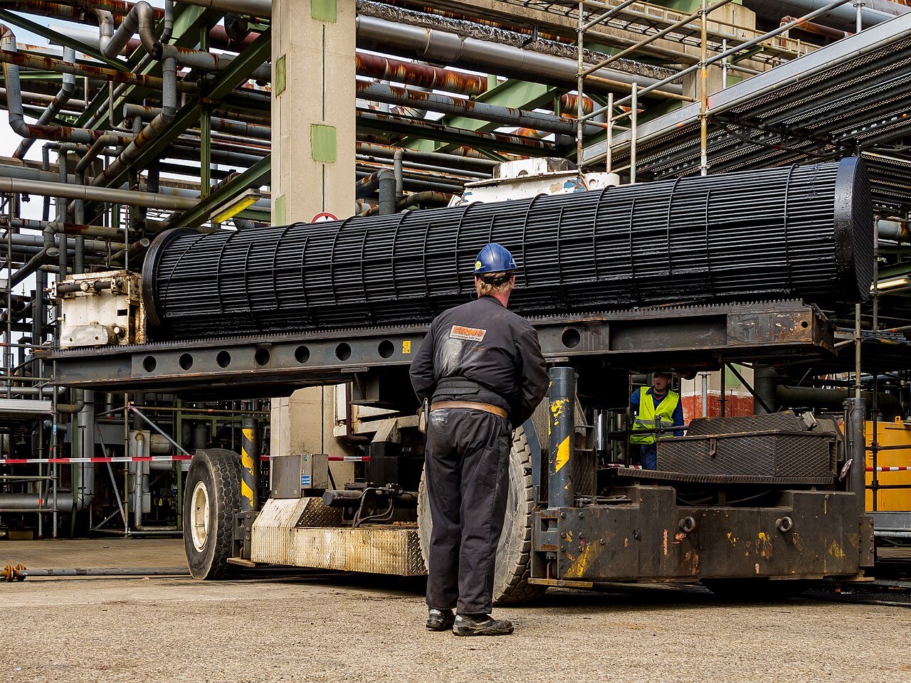
Heat exchanger leak online repair stops a leak on a shell-and-tube, plate or air-cooled exchanger while the unit stays in service and the process keeps running, so production is not interrupted.
This guide is for process engineers, maintenance engineers and operations supervisors running exchangers in refineries, petrochemical plants and power facilities in Indonesia. It maps where exchangers leak, which methods work with the unit in service, and why a tube leak bridging two process sides is a contamination question first.
What Is Heat Exchanger Leak Online Repair?
Heat exchanger leak online repair is the containment or isolation of a leaking exchanger component — a tube, a tube-to-tubesheet joint, a head or shell gasket, a nozzle weld, a plate gasket or an air-cooler header plug — without depressurising, draining or opening the exchanger. Depending on the leak path, the method is tube plugging, sealant injection into a joint, an external clamp over a flange or weld, or a combination.
The technique changes the local pressure boundary so the leak stops; it does not remove the exchanger from the process. It is used when stopping the unit — lost throughput, thermal cycling, restart risk and flaring — costs more than a controlled repair on a live machine. It is not a substitute for retubing or replacement. Our overview of online leak sealing technology and methods covers the general family; this page applies it to exchangers.
Why Exchanger Leaks Behave Differently From Piping Leaks
A pipe carries one fluid. An exchanger separates two, usually at different pressures and often with different chemistry, and that changes the engineering and the safety case.
- Two fluids, one pressure boundary. A shell-and-tube exchanger separates tube-side and shell-side fluids with a metal wall and two tube-to-tubesheet joints, so a leak is a potential mixing event, not just lost inventory.
- The leak path is usually internal. Most exchanger leaks are found from pressure trends, cooling water conductivity or product contamination, so the diagnosis is an inference before any repair starts.
- The driving force is differential pressure. A 10 bar tube side against a 3 bar shell side gives a 7 bar driving force in one direction only, and direction decides which fluid enters which.
- Thermal cycling keeps moving the joints. Rolled tube joints and bolted joints that were tight when cold may weep when hot, so a seal must survive the operating cycle, not just the moment of injection.
- Access is limited to the channel or header. An exchanger offers little reach, and what can be reached decides what can be repaired online.

Thermal movement is not a side issue on exchangers — the expansion a compensator absorbs on a pipe run acts directly on exchanger gaskets, tube joints and bolted connections, so a seal must hold across the operating cycle.
Where Heat Exchangers Leak: A Location Map
Each leak location has its own mechanism, method and hard limit.
| Leak type | Method | Possible during operation? | Conditions |
|---|---|---|---|
| Tube wall (single tube) | Tapered or welded tube plug | Sometimes | Process engineer must confirm the leak path; a tube bridging two different process sides needs analysis first |
| Tube-to-tubesheet joint | Plugging, joint re-expansion or sealant injection | Sometimes | Joint must be reachable through the channel or header; plugging the tube body does not cure it |
| Head, channel cover or bonnet gasket | External gasket clamp or injected sealant | Often | Flange faces and bolts sound; a gasket failed across its full width will not be held |
| Shell flange gasket | External gasket clamp or injected sealant | Often | Access around the shell flange and a defined maximum injection pressure |
| Nozzle-to-shell or nozzle-to-header weld | Enclosure or clamp with injected sealant | Sometimes | Surrounding material full thickness; a crack or wall loss needs a weld repair |
| Plate gasket (plate heat exchanger) | Gasket replacement after opening the pack | Rarely | The leak path is inside the pack between plates; the pack usually has to be opened |
| Air-cooler header plug or tube-to-header joint | Plug replacement, plugging or sealant injection | Sometimes | Header access available and the process side allows it; the allowed plug count applies |
Tube Plugging: What It Can and Cannot Do
Plugging a tube is the oldest online exchanger repair. A tapered plug is driven into the tube end, or welded in place, and the tube is isolated from both sides. The exchanger stays in service until the next planned shutdown.
Plugging does not restore the exchanger. Every plugged tube removes heat transfer area and adds pressure drop, so duty falls. Plants therefore set a limit on how many tubes may be plugged before retubing, agreed by the process engineer.
- Confirm which side the leak is on and the direction of flow across it before plugging.
- Confirm the leak is in the tube body, not the tube-to-tubesheet joint; a plug does not repair a joint leak.
- Confirm the plug is rated for the tube-side design pressure and temperature.
- Record the tube position, so the running count against the allowed limit is maintained.
- Re-check outlet temperatures after plugging, because lost area shows up as a duty shortfall.
The Cross-Contamination Rule That Overrides Everything Else
This is the point that separates a competent exchanger repair from a dangerous one. In a shell-and-tube exchanger the tube side and shell side normally carry different fluids, and a tube leak connects them. If the tube side is at higher pressure, process fluid enters the shell side; if the shell side is higher, cooling water or a utility enters the process.
Neither direction is merely lost product. Process fluid entering a cooling water loop contaminates the cooling tower, the return headers and every exchanger downstream. Cooling water entering a hydrocarbon process introduces water that can corrode, form hydrates or poison catalyst, and in hydrogen or amine service a leak can upset a whole treating unit.
A tube leak that bridges a high-pressure side and a low-pressure side must not be plugged on the strength of a visible leak alone. Plugging removes the tube from service, but it does not establish what has already crossed, or whether contamination requires the exchanger to be isolated. Those are process decisions.
- The process engineer must confirm the two fluids, the differential pressure direction, and the consequence of mixing in both directions.
- Where both sides carry the same fluid, such as a feed and effluent interchanger, plugging is routine.
- Where the sides are different fluids, or one is a utility, the leak is a process safety event for the process engineer and the integrity function.
- Plugging is accepted only after the leak path is positively identified; a suspected tube leak that is actually a joint leak will keep passing fluid.
- Where contamination has occurred, the repair and the clean-up are separate tasks; the plug stops flow, it does not restore the system.
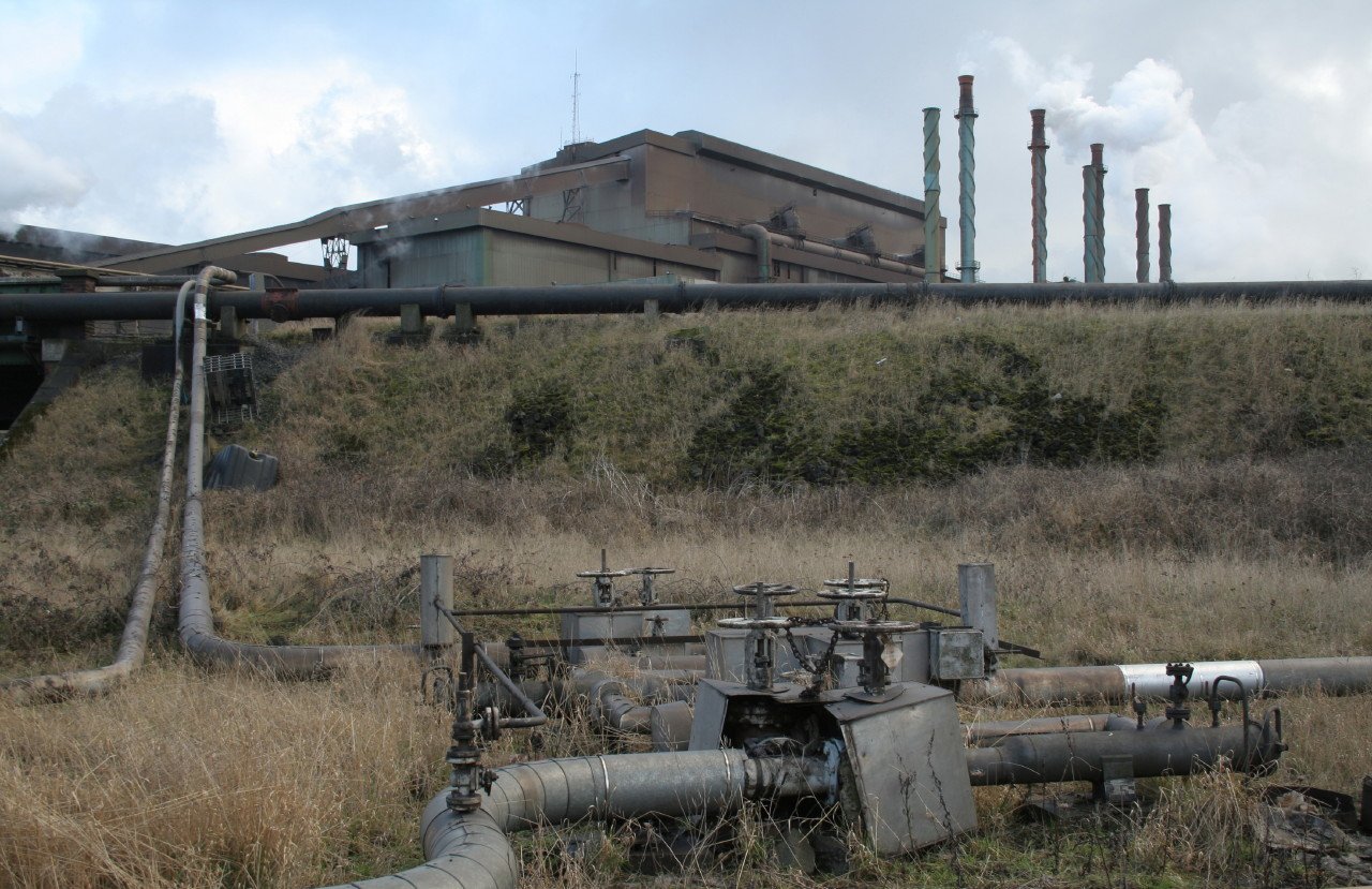
The piping around an exchanger is why a tube leak matters beyond the exchanger itself: process fluid crossing into a cooling water or utility circuit travels through headers and downstream equipment before anyone notices.
Gasket and Joint Leaks: Head, Shell and Plate
Exchanger gasket leaks are the most favourable case for online repair, because they sit on the outside of the pressure boundary and are accessible. A weeping bonnet, channel cover, shell flange or floating head joint can often be contained with an external gasket clamp — a bolted enclosure that surrounds the joint and seals against both flange faces — or with sealant injected into the gasket path.
Two cautions apply. An external clamp contains the leak at the outer edge of the joint; if the gasket has failed across its full width, fluid may travel through the clamp’s own sealing surfaces and the clamp will not hold. Bolted joints are also torqued to a specified value, so disturbing them on a live unit is a documented decision. The flange method is covered on our flange leak online sealing page, and injection pressures follow our high pressure leak sealing solution guidance.
Plate heat exchangers are a separate case. The plate pack is held by tie bolts and each plate is sealed by a gasket in a groove, so a leaking plate gasket is an internal leak between adjacent channels and generally cannot be sealed from outside. The pack must be depressurised, opened and re-gasketed. The tooling is described in our heat exchanger maintenance equipment notes.
When sealant is used on any exchanger joint, the chemistry must match the service. A sealant chosen for a water circuit is not automatically suitable for hot hydrocarbon or amine, as our online leak sealing sealant selection guide explains.
Nozzle, Small-Bore and Air-Cooler Leaks
Nozzle-to-shell and nozzle-to-header welds are pressure-boundary welds. A leak there is not a gasket problem and cannot be resolved by tightening anything. Where the surrounding material is sound and the defect is a local pinhole, an enclosure or clamp with injected sealant can contain it while the exchanger runs. Where the flaw is a crack or is associated with significant wall loss, containment is temporary at best and the weld needs a proper repair. Weld repair practice follows guidance from bodies such as TWI.
Air coolers present their own geometry: the leak points are the tube-to-header joint, the header plug and the tube body. Header plugs are designed to be removed for cleaning, so a leaking plug can sometimes be replaced or sealed with the header in service. Tube-to-header and tube-wall leaks follow the same logic as a shell-and-tube unit.
Small-bore connections — vents, drains, instrument tappings and sample points — are frequent leak sources because they are thin-walled, often unsupported and subject to vibration. They are also where a clamp failure has the worst consequences, because a fitting that fails completely can release a full-diameter jet. Small-bore clamps must be rated and restrained, never improvised, and the same discipline applies to valves on the isolation path, as described under valve online leak sealing.

Manifolds, drains and instrument connections are where exchanger clamp work concentrates — thin-walled, vibration-loaded and often unsupported, these small-bore fittings carry the same pressure as the exchanger body.
Standards and Documentation Behind the Repair
Exchanger repair sits inside a documented framework. ASME PCC-2, published by ASME, governs repair of pressure equipment and piping in service, including the temporary pressure boundary that a clamp creates. API 660 covers shell-and-tube exchangers and API 661 covers air-cooled exchangers, and both are catalogued through the API standards programme. ASME B31.3 applies to connected piping, and fitness-for-service assessment of the shell or channel wall is framed by API 510 and API 570.
Corrosion and materials assessment commonly follows guidance associated with AMPP, formed from the merger of NACE International and SSPC. That matters on exchangers because failures are so often corrosion-driven: chloride stress corrosion cracking in stainless tubes, erosion at tube inlets and galvanic effects at the tubesheet.
The repair record should include the exchanger tag, the two fluids and their pressures and temperatures, the identified leak path, the method and its limit, and the verification results. In Indonesia, exchanger work in oil and gas facilities also sits inside the framework administered by Ditjen Migas.
Verification After a Live Exchanger Repair
Verification is a separate activity with its own hold point. The repair is not accepted because the visible leak has stopped.
- Visual inspection of the enclosure or sealed joint after injection pressure is released, and again at operating temperature.
- Leak detection around the repair using a portable combustible gas indicator or a cooling water conductivity check.
- Process-side monitoring — outlet temperature, pressure drop and, for a tube leak, the cooling water conductivity trend.
- Direction check on the differential pressure across the repaired boundary, because a leak that reverses under a different operating case will not stay sealed.
- Duty check against design outlet temperatures, especially after plugging, to confirm lost area has not pushed the unit outside its duty.
- Documentation and scheduling — the repair record entered into the exchanger history, with retubing scheduled at the next turnaround.
Key Takeaways
- Online repair covers tubes, tube-to-tubesheet joints, head and shell gaskets, nozzle welds, plate gaskets and air-cooler header plugs, but the method depends on whether the leak path is reachable.
- A tube leak bridging a high-pressure and a low-pressure side is a contamination event, not merely lost product, and must not be plugged without the process engineer’s analysis.
- Plugging a tube restores the seal but reduces heat transfer area and raises pressure drop, so the plug count must stay within a limit agreed against the required duty.
- External gasket clamps and injected sealant suit head, channel, bonnet and shell flange leaks, provided the flange faces and bolts are sound.
- Plate exchanger gasket leaks are internal to the plate pack and generally require the pack to be opened and re-gasketed.
- ASME PCC-2, API 660, API 661, API 510 and API 570 frame the repair and the fitness-for-service assessment, with corrosion practice following AMPP guidance.
- Verification is a hold point: visual check, gas or conductivity detection, process monitoring and a documented repair record.
FAQ: Heat Exchanger Leak Online Repair
Can a heat exchanger leak be repaired while the unit is running?
Yes, for some leak paths. Head, channel, bonnet and shell flange gasket leaks can often be contained with an external clamp or injected sealant, and a single tube can sometimes be plugged. Internal plate pack leaks cannot be repaired without depressurising and opening the exchanger.
Why is plugging a leaking tube sometimes not allowed?
If the tube bridges two different process sides, the leak is a contamination path between them, not simply a loss of product. Plugging may remove the path but does not establish what has already crossed. The process engineer must confirm the leak path and the mixing consequences first.
How many tubes can be plugged before the exchanger must be retubed?
There is no universal number. Each plugged tube removes heat transfer area and raises pressure drop, so the allowable count is set by the process engineer against the required duty and acceptable outlet temperatures. Once that limit is reached the exchanger should be retubed or replaced.
What standards apply to heat exchanger leak repair?
ASME PCC-2 governs repair of pressure equipment and piping in service, including the temporary boundary created by a clamp. API 660 covers shell-and-tube exchangers and API 661 covers air-cooled exchangers. Fitness-for-service assessment follows API 510 for vessels and API 570 for piping, with corrosion guidance from AMPP.
How is a live exchanger repair verified after it is completed?
Verification is a defined hold point. The enclosure or sealed joint is inspected once injection pressure is released and again at operating temperature. Gas detection or cooling water conductivity confirms no leakage, process trends such as outlet temperature and pressure drop are checked, and lost duty is assessed after plugging.
Leak still running and the plant is on limited time? Our response desk is staffed around the clock. Message the emergency team on WhatsApp or send a site brief with the line ID, medium, operating pressure and temperature, and we will confirm scope before mobilisation.
Conclusion
Heat exchanger leak online repair is genuinely useful and genuinely bounded. It can contain a head, channel or shell flange leak, isolate a single tube or resolve a header plug problem while the unit keeps running. It cannot reach a plate pack gasket that has failed between plates, cannot restore lost heat transfer area, and cannot decide on its own whether a tube bridging two process sides may safely be plugged. Knowing which case you are in is the first engineering decision.
The second decision is about contamination, and it is the one most often skipped under production pressure. A tube leak between a high-pressure side and a low-pressure side moves fluid from one system into another, and the consequence travels through headers, cooling towers and downstream equipment long before it is visible. Containment that ignores that path is not a repair. If your site has an exchanger leak that must be contained without taking the unit out of service, our emergency leak online sealing team can triage it against the map above, and the online leak sealing services in Indonesia page explains how mobilisation and on-site permits are handled.