Flange Leak Online Sealing: Technical Guide for Industrial Applications
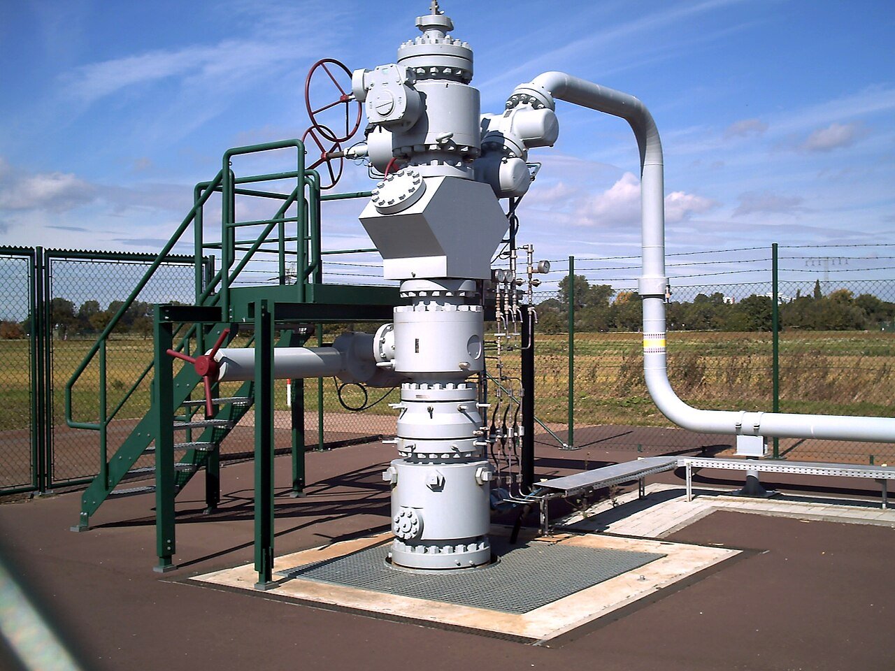
Flange leak online sealing is the engineered repair of active leaks at flanged pipe joints — the most common type of pressurized connection in oil and gas, petrochemical, refinery, and power generation piping systems — while the system remains at full operating pressure and temperature. Flanged joints are ubiquitous in industrial piping: every valve, instrument connection, pump, compressor, vessel nozzle, and piping spool has flanged connections, and each represents a potential leak point as gaskets age, bolts relax, and flange faces corrode.
In Indonesia’s oil and gas and industrial sector, flange leaks account for the largest share of online sealing interventions. A leaking flange on a high-pressure hydrocarbon line is a process safety incident that demands immediate, engineered response — not a temporary patch, and not a production shutdown if a proper online repair solution can be engineered and deployed. Sipinus provides flange leak online sealing services across Indonesia with the engineering depth and response speed that demanding industrial applications require.
For the broader context of online sealing methodology, read our pillar guide on emergency leak online sealing. For the full spectrum of emergency repair technologies available, read our guide on emergency leak online repair solution.
Why Flanged Joints Leak
Gasket Degradation
The gasket is the primary sealing element of a flanged joint. Over time, gasket materials — spiral wound stainless/graphite, ring type joint (RTJ), full-face rubber, PTFE envelope, compressed fiber — degrade through: thermal cycling that causes creep relaxation in the gasket material; chemical attack by the process fluid; radiation damage in nuclear service; and simple aging that reduces compressive resilience. A degraded gasket loses its ability to maintain a leak-tight seal even when bolt load is maintained, and the result is a progressively worsening flange leak.
Bolt Relaxation and Insufficient Bolt Load
Flange bolts must maintain sufficient compressive load on the gasket throughout the service life of the joint. Bolt load is lost through: thermal cycling (differential thermal expansion and contraction between pipe, flange, and bolts); gasket creep (the gasket compresses further under sustained load, reducing the bolt extension that maintains load); vibration; and corrosion of bolt threads or nut-face bearing surfaces. When bolt load drops below the minimum seating stress required by the gasket, the joint leaks.
Flange Face Damage and Corrosion
The sealing surface of the flange face must be within the surface finish and flatness tolerances required by the gasket type. Radial scratches across the sealing surface, corrosion pitting on the flange face, or mechanical damage from improper gasket removal create leak paths that prevent the gasket from sealing regardless of bolt load. These defects are typically discovered during maintenance when the joint is disassembled — but the resulting leak when the joint is reassembled requires immediate attention.
Thermal Shock and Waterhammer
Rapid temperature changes — steam breakthrough into a water-flooded line, emergency shutdown followed by rapid restart, thermal relief events — create transient stress cycles that can crack brittle gaskets, break spiral wound winding, or cause sudden bolt load loss. Waterhammer (hydraulic shock in liquid systems) applies impulse loading to flanged joints that can unseat gaskets even in recently tightened joints.
Wrong Gasket Specification
Using the wrong gasket material, incorrect dimensions, or an incompatible gasket design for the pressure class and service conditions is a common root cause of persistent flange leaks. A CAF (compressed asbestos fiber) replacement in a high-temperature steam service, a rubber sheet gasket in a solvent service, or a standard spiral wound gasket without inner ring in a high-pressure application — all will leak under service conditions. Online sealing addresses the immediate containment problem; the underlying specification error must be corrected at the next turnaround.
Flange Leak Online Sealing Technology: Encapsulation Clamps
The standard engineering solution for flange leak online sealing is the split encapsulation clamp — a purpose-engineered two-piece or multi-piece clamp that wraps around the entire flanged joint, creates an annular cavity around the leaking gasket, and enables sealant injection to fill the leak path and restore pressure-tight containment.
Clamp Design Elements
A properly engineered flange encapsulation clamp incorporates:
- Body halves: Two (or more) machined steel body sections that close around the flange pair. The bore is machined to match the flange OD with appropriate clearance for sealant fill. The clamp must bridge both flanges and the gasket zone fully.
- End seals: Elastomeric or injection-type end seals that close the annular cavity at both ends of the clamp, preventing sealant escape during injection and providing the primary static sealing interface between clamp and pipe OD.
- Injection fittings: Multiple injection ports distributed around the clamp body allow sealant to be injected uniformly into the annular cavity, ensuring complete fill without voids.
- Vent fittings: Vent ports allow air and any escaping process fluid to exit the cavity as sealant fills it — ensuring the cavity is fully charged with sealant rather than partially filled with trapped air or gas.
- Bolting: High-tensile bolt sets secure the clamp body halves together under the forces generated by operating pressure acting on the end seal areas.
Pressure Rating
The clamp is engineered to contain the maximum allowable operating pressure (MAOP) of the pipeline, applying ASME PCC-2 design methodology and the appropriate safety factors. The bolting and body wall thickness calculations confirm the clamp is adequate for the operating pressure class. Clamps are routinely engineered for ASME Class 600, 900, 1500, and 2500 flange ratings and equivalent metric pressure classes.
Standard vs. Custom Clamps
For common flange sizes and pressure classes (NPS ½” to 48″, Class 150 to 1500), Sipinus maintains a pre-engineered clamp design library that reduces fabrication time significantly. Custom clamps are engineered for non-standard flange configurations, unusual dimensions (large diameter pipelines, special alloy flanges with modified ODs), or access-constrained locations requiring modified clamp geometry.
Sealant Injection for Flange Leaks
Sealant selection for flange leak sealing follows the same engineering principles as for other online sealing applications — with flange-specific considerations:
- Hydrocarbon service (gas, oil, condensate): Hydrocarbon-compatible sealants that resist dissolution and maintain integrity in the presence of process fluid. For high-pressure gas service, a sealant with low permeability to the gas molecule is required to prevent slow bleed-through.
- Steam service: High-temperature sealants rated to the saturated or superheated steam temperature — typically 300°C to 550°C depending on system parameters. Steam sealants must withstand sustained hydrothermal exposure without hydrolytic degradation.
- Cryogenic service (LNG, nitrogen): Sealants that remain flexible and maintain adhesion at cryogenic temperatures (-160°C to -196°C). Standard ambient-temperature sealants become brittle and lose sealing effectiveness at cryogenic conditions.
- Sour service (H₂S): Sealants confirmed compatible with H₂S environments per NACE MR0175 requirements, resistant to sulfide stress cracking mechanisms.
- Chemical service: Appropriate chemical resistance to the specific process chemical — sulfuric acid, caustic, chlorine compounds, organic solvents. Compatibility testing data must support the sealant selection for unusual chemical services.
Installation Procedure for Flange Encapsulation Clamps
The installation of a flange leak sealing clamp follows a defined procedure under the approved work method statement:
- Preparation: Clean the flange OD area where end seals will contact the pipe. Remove loose corrosion, scale, and debris from the clamp installation area. Apply anti-galling compound to clamp bolts.
- Clamp positioning: Position the lower clamp half under the flanged joint. Thread the installation bolts through the lower half.
- Upper half installation: Position the upper clamp half over the flanged joint. Close the two halves together, engaging the end seals on the pipe OD at both ends of the clamp.
- Bolting: Tighten the clamp bolts in a cross-pattern sequence to the specified torque or tension, ensuring uniform end seal compression and clamp body closure.
- Vent check: Confirm vent and injection fittings are open and accessible.
- Sealant injection: Connect the injection pump to the first injection port. Inject sealant at controlled pressure, monitoring injection pressure and volume. Continue until sealant appears at the vent port on the opposite side of the clamp.
- Sequential port injection: Move to each injection port in sequence, ensuring complete sealant fill of the cavity.
- Final pressurization: After all ports are charged, apply final injection pressure to confirm sealant has fully displaced the leak path and the flange is sealed.
- Leak verification: Confirm zero visible leak from the flanged joint and clamp assembly. Check all injection and vent fittings for leak-tightness.
- Documentation: Record injection pressures, volumes, sealant batch numbers, and installation photographs.
Special Applications: Large-Bore and Subsea Flange Sealing
Large-Bore Pipeline Flanges
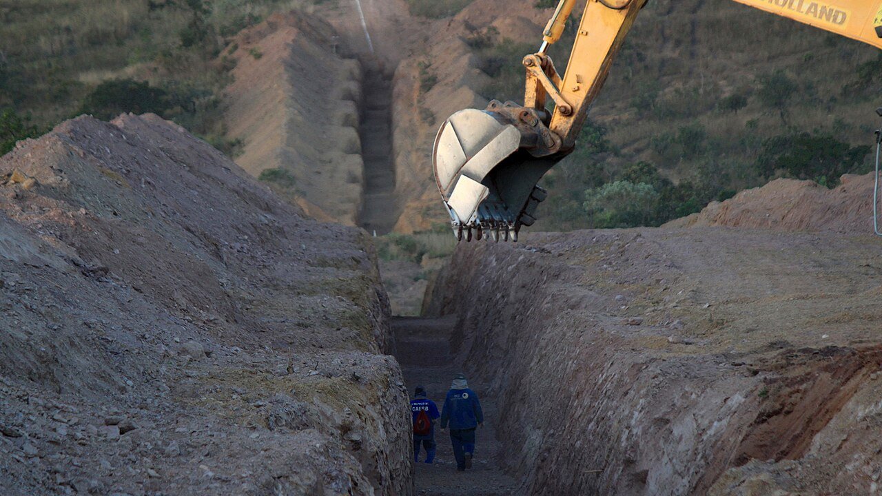
Flanges on large-diameter transmission pipelines (24″ to 60″ NPS) require correspondingly large encapsulation clamps — substantial structures that may weigh hundreds of kilograms and require mechanical handling for installation. The engineering and fabrication of large-bore flange clamps follows the same principles as smaller units but with more stringent attention to handling, bolting sequence, and uniform end seal engagement around the full circumference. For more on pipeline-specific leak scenarios, read our guide on pipeline emergency leak repair.
Subsea Flange Leaks
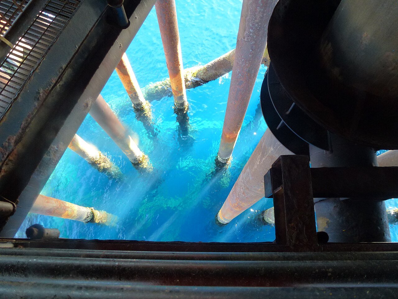
Flanged connections on subsea pipelines, manifolds, and riser bases are accessed via ROV or diver. Subsea flange encapsulation clamps use hydraulically actuated closure mechanisms (for ROV installation) or diver-friendly manual bolting designs. Subsea sealant injection is performed using ROV-mounted pump skids or diver-operated tools. The engineering requirements are identical to surface applications, but the installation tooling and procedure are adapted for the subsea environment.
Post-Sealing Monitoring and Turnaround Planning
After a flange leak sealing clamp is installed, the following monitoring and planning actions are recommended:
- Initial monitoring period: Check the installation for any sealant weep or process fluid escape at 1 hour, 8 hours, and 24 hours after installation. Any signs of instability require immediate re-assessment.
- Periodic inspection: Include the clamp in routine plant inspection rounds — visual check for any external corrosion of the clamp body, bolt condition, and any signs of sealant extrusion.
- Turnaround scope inclusion: Register the clamp installation in the plant’s turnaround planning system as a scope item for gasket replacement (or flange face refacing if face damage is the root cause) and clamp removal. The online seal is a bridge to the planned permanent repair.
- Root cause documentation: Record the assessed root cause of the flange leak in the maintenance management system to inform future gasket material specifications, retorquing programs, and insulation inspection schedules.
For the full financial case for proactive flange leak management versus reactive emergency response, read our analysis of emergency leak repair cost and downtime reduction. For industry-specific guidance in Indonesia’s oil and gas sector, read our guide on emergency leak repair for oil and gas Indonesia.
Frequently Asked Questions about Flange Leak Online Sealing
Can a clamp be installed on an insulated flange?
Yes, but the insulation must be removed from the flange and adjacent pipe in the clamp installation zone before the clamp can be fitted. The extent of insulation removal is defined in the clamp drawing. Insulation should be reinstated after clamp installation to maintain thermal performance and protect the clamp from external corrosion.
What happens to the clamp when the gasket is replaced at turnaround?
The clamp is removed, the sealant cleaned from the clamp cavity and flange OD, the new gasket is installed, the joint is reassembled and retorqued, and the clamp can be cleaned and returned to stock for future use (if the design is reusable) or scrapped. Clamp removal is straightforward — unbolting the clamp halves and separating them from the flange.
What flange types are covered by online sealing?
Weld-neck flanges, slip-on flanges, socket-weld flanges, lap joint flanges, blind flanges with nozzle leaks, orifice flanges, and spectacle blinds — all can be addressed with appropriately designed encapsulation clamps. The clamp design is specific to the flange type and dimensional standard (ASME B16.5, ASME B16.47, DIN, JIS, API 6A, etc.).
How long does flange online sealing take?
For a standard ASME B16.5 flange in an accessible location using a pre-engineered clamp from stock, installation typically takes 2–4 hours including preparation, installation, injection, and verification. Custom clamp fabrication for non-standard flanges adds 24–72 hours to the total response time.
Related Articles: Emergency Leak Online Sealing | Valve Online Leak Sealing | High Pressure Leak Sealing Solution | Online Leak Sealing Technology & Methods | Pipeline Emergency Leak Repair